
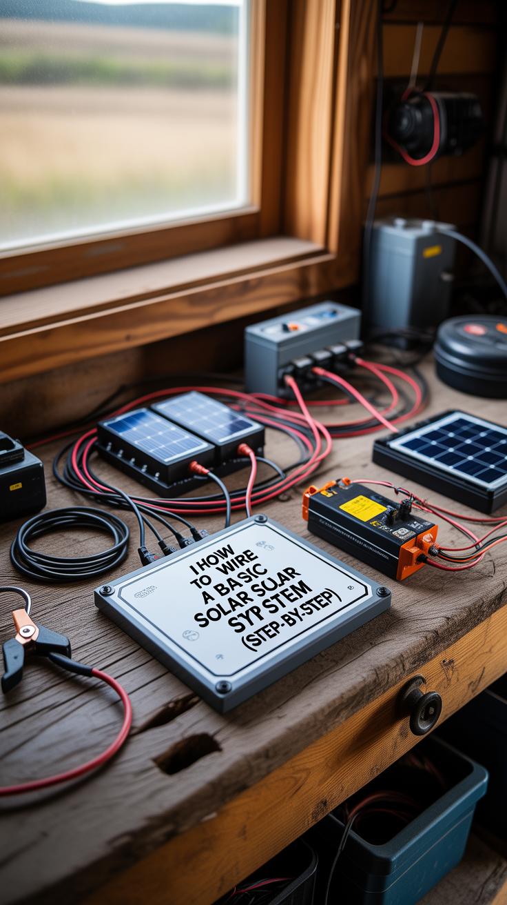
How to Wire a Basic Off-Grid Solar System Safely (Step-by-Step)
Wiring your first solar setup can feel intimidating—but it doesn’t have to be. This guide shows how to wire a basic off-grid solar system safely (step-by-step) using clear, practical wiring logic: panels → charge controller → battery → inverter → loads. You’ll learn where fuses go, how to size wire, how to avoid common fire and shock hazards, and how to test everything before you power up.
Off-grid solar isn’t only about electricity. It’s about resilience: keeping lights, refrigeration, communications, and critical devices running when the grid is down. Many people building a small solar system also strengthen other essentials like water and food storage alongside their power plan. If you’re building a complete preparedness baseline, resources like The Self-Sufficient Backyard can help you think through the bigger picture beyond wiring.
Safety-first mindset for off-grid solar wiring
Before you touch a wire, treat your system like any other electrical installation: errors can cause battery fires, melted conductors, arc flashes, and equipment damage. The good news is that a basic off-grid system is very manageable when you follow standard safety habits.
Core safety rules that prevent most failures
- De-energize before working: Cover panels or disconnect PV first; disconnect batteries last and reconnect batteries first (more on sequence later).
- Fuse or breaker every source of current: PV strings, battery positive, and inverter feed should all have protection sized to wire and equipment.
- Use proper wire types and terminations: PV wire for panels, stranded copper for battery/inverter, and correctly sized lugs with a real crimper.
- Prevent accidental shorts: Keep tools insulated, remove jewelry, and never lay metal objects on battery tops.
- Label and secure everything: Strain relief, grommets through metal, cable clamps, and clear polarity markings reduce “mystery” faults.
A practical note on codes and liability
If this is for a cabin, RV, shed, or emergency backup, local rules may still apply—especially if you hardwire AC circuits. When in doubt, have a licensed electrician review your AC side, bonding, and grounding.
System overview and wiring diagram logic
A “basic off-grid solar system” usually means one of these common configurations:
- 12V or 24V DC battery bank
- Solar panels feeding a charge controller (PWM or MPPT)
- Battery bank feeding an inverter (DC → AC)
- Loads connected either to:
- AC output of inverter (standard household appliances)
- DC loads via a fused DC distribution (lights, USB, fans), optional
The simplest safe layout (conceptual flow)
- PV Array → PV Disconnect/Fuse → Charge Controller (PV input)
- Charge Controller (battery output) → Battery Fuse/Breaker → Battery Bank
- Battery Bank → Inverter Fuse/Breaker → Inverter
- Inverter → AC breaker panel / outlets / extension loads
- Grounding/Bonding where appropriate (equipment grounds tied together; DC negative bonding depends on inverter/controller design)
Why this order matters
The charge controller is the “traffic cop” between panels and batteries. The inverter is the biggest load and can pull hundreds of amps at 12V, so it requires short, thick cables and solid overcurrent protection.
Tools, materials, and components you’ll need
You’ll move faster (and safer) if you gather everything first.
Essential tools
- Digital multimeter (DC volts, AC volts, continuity)
- Wire stripper/cutter for small gauge wire
- Lug crimper for battery cables (hydraulic crimper preferred)
- Torque wrench or torque screwdriver (for controller/inverter terminals)
- Heat gun + adhesive heat shrink
- Label maker or tape + marker
- PPE: safety glasses, insulated gloves (especially around batteries)
Common components for a beginner system
- Solar panels (one or more)
- Mounting hardware (roof/ground rack)
- Charge controller (PWM or MPPT)
- Battery (LiFePO4 or lead-acid)
- Inverter (pure sine wave preferred for sensitive devices)
- Fuses/breakers and holders (PV and battery-rated)
- Busbars (positive and negative, optional but clean)
- Proper wire (PV wire, battery cable, grounding conductor)
- MC4 connectors (if custom PV leads needed)
- Cable glands, conduit, clamps
Expert quote format:
“As many off-grid instructors emphasize, ‘your wiring is your safety system.’ In preparedness circles, power is only one pillar—building a complete plan often includes water and food resilience too. Resources like The Lost SuperFoods are commonly referenced because they focus on long-term, shelf-stable options that complement an off-grid power setup.”
Choosing voltages and sizing basics without guesswork
You don’t need to be an electrical engineer, but you do need three sizing concepts: voltage, current, and wire/fuse sizing.
Pick a system voltage that fits your goals
- 12V systems: Great for small setups (lights, charging, small inverter loads). Higher current means thicker cables for bigger inverters.
- 24V systems: Better for medium systems. Current is cut roughly in half vs 12V for the same power.
- 48V systems: Common for full cabins and large inverters, but wiring and equipment choices get more advanced.
If your inverter is 1000–2000W and you plan longer cable runs, 24V is often a sweet spot.
Understand the current draw (why cables get big fast)
Use: Amps = Watts ÷ Volts (roughly, on DC side).
Example: 1500W inverter load on 12V:
- 1500 ÷ 12 = 125A (not counting inverter losses)
That can easily exceed 150A peak.
This is why inverter cables must be short and heavy, and why the battery fuse and disconnect matter.
Wire gauge and voltage drop basics
- For PV strings: keep voltage drop low, but PV currents are often moderate (unless many panels in parallel).
- For battery-to-inverter: voltage drop is critical; high current makes small losses turn into heat.
A safe beginner rule: use the inverter manufacturer’s cable size guidance for your inverter’s max current and cable length, then fuse to protect that cable.
Wiring order and safe connection sequence
When people damage controllers, it’s often due to connecting PV before the controller “sees” the battery. Many controllers require battery voltage to initialize.
Safe connection sequence (typical best practice)
- Mount everything (controller, inverter, disconnects, busbars) first.
- Wire controller to battery (through a correctly sized fuse/breaker).
- Power the controller and confirm it detects battery voltage.
- Wire PV to controller (through PV fuse/disconnect; cover panels while working).
- Wire inverter to battery (through inverter fuse/breaker and disconnect).
- Connect loads (AC and/or DC).
- Final checks, then energize in a controlled way.
Safe disconnection sequence
- Turn off loads and inverter.
- Disconnect PV (or cover panels).
- Disconnect inverter from battery.
- Disconnect controller from battery last.
This sequence reduces the chance of unwanted arcs and protects the controller.
Wiring the solar panels to the charge controller
This is your PV side. The two big decisions are series vs parallel wiring and protection/disconnect strategy.
Series vs parallel (the practical meaning)
- Series (voltages add): Higher voltage, same current. Often better for MPPT controllers and long runs (smaller wire, less loss).
- Parallel (currents add): Same voltage, higher current. Needs larger wire and typically requires fusing for each string.
Most beginners using MPPT do well with a higher-voltage PV string (as allowed by controller limits).
PV disconnects, fuses, and combiner basics
- If you have one string, you may use a single PV-rated disconnect/breaker.
- If you have two or more strings in parallel, each string generally needs its own fuse/breaker before combining (combiner box), so a fault in one string doesn’t get backfed by others.
Step-by-step: panel wiring to controller
- Confirm controller PV input limits (max PV voltage, max current). Do not exceed them in cold weather conditions.
- Decide series/parallel configuration.
- Run PV wire from array to a PV disconnect/combiner (if used).
- From disconnect/combiner, run PV +/− to controller PV terminals.
- Torque terminals to spec; tug-test wires.
- Label PV polarity and route cables away from sharp edges and heat.
Quick safety checks
- Measure PV open-circuit voltage (Voc) before connecting.
- Verify correct polarity at the controller input.
- Use cable clips and UV-rated ties outdoors; avoid indoor zip ties on roofs.
Wiring the charge controller to the battery bank (the heart of the system)
This connection determines whether your batteries charge safely and whether your controller survives.
Key rule: battery-side protection close to the battery
Place a fuse or breaker on the positive battery lead from the controller, as close to the battery as practical. The purpose is to protect the wire in case it shorts.
Step-by-step: controller to battery wiring
- Choose wire size based on controller output current and run length.
- Install a DC-rated breaker or fuse on the controller positive lead near the battery (or on a positive busbar fed close to the battery).
- Route cables neatly; avoid loose coils.
- Connect controller negative to battery negative (or negative busbar).
- Connect controller positive through the breaker/fuse to battery positive.
- Turn on the breaker / insert fuse.
- Confirm controller detects correct battery voltage and charging mode.
Battery chemistry considerations (don’t skip this)
- LiFePO4: Often requires specific charge voltages and may use a BMS. Configure the controller profile correctly.
- Lead-acid (flooded/AGM/gel): Needs proper absorption/float settings; flooded batteries also need ventilation.
If you’re integrating solar into a broader off-grid preparedness plan, water storage and filtration can matter as much as watt-hours. Many households pair power projects with resources like SmartWaterBox to help think through water readiness alongside energy.
Wiring the battery to the inverter (high-current zone)
This is where the biggest currents flow, and where most dangerous shorts occur. Treat it like working on a car battery—except often much larger.
Critical rules for inverter wiring
- Keep inverter DC cables short and thick (often the shortest run in your system).
- Use proper lugs, crimped and heat-shrunk.
- Add a battery disconnect you can reach quickly.
- Add a Class T fuse (or appropriately rated DC fuse) sized to protect the cable and inverter, placed near the battery.
Step-by-step: inverter wiring
- Mount inverter with airflow clearance; keep away from battery off-gassing (especially lead-acid).
- Install a DC-rated disconnect switch (optional but strongly recommended).
- Install the inverter fuse on the positive cable close to the battery/busbar.
- Make battery cables:
- Measure length carefully
- Crimp lugs with a real crimper
- Seal with adhesive heat shrink
- Connect inverter negative to battery negative (or negative busbar).
- Connect inverter positive through the fuse and disconnect to battery positive.
- Double-check torque on terminals (loose connections cause heat and failure).
- Only then power on the inverter with no loads first.
Problem-solution bridge
Struggling with “how big should my off-grid system be” before committing to hardware? Educational build-guides like Energy Revolution System can help you visualize layouts and power budgeting—useful for avoiding undersized cables, fuses, and batteries from the start.
Grounding, bonding, and surge protection basics (without overcomplicating)
Grounding is where many DIY builds go sideways because terms are mixed up. Here’s a simplified, safety-forward approach.
Key definitions (simple)
- Equipment grounding: Connecting metal chassis parts (panel frames, inverter case) to a grounding conductor so a fault trips protection instead of energizing metal.
- Bonding: Ensuring all metal parts are electrically connected so they’re at the same potential.
- System grounding: Referencing a conductor (often DC negative or AC neutral) to earth—depends on equipment design.
What you can safely do on most small systems
- Ground panel frames and racking with appropriate grounding lugs and wire.
- Ground inverter chassis to the same grounding system.
- Use a grounding rod where applicable for fixed ground-mount systems (local rules vary).
- Consider DC/AC surge protection if you’re in lightning-prone areas.
Important caution
Some inverters bond neutral to ground internally; others do not. Some systems require a switching neutral-ground bond depending on whether you’re using shore power or a generator. If you’re unsure, consult the inverter manual and, for permanent installs, an electrician.
Testing and commissioning your system safely
Testing isn’t optional. It’s how you catch reversed polarity, loose connections, and incorrect voltages before something fails.
Step-by-step commissioning checklist
- Visual inspection
- No exposed copper
- Cables supported and protected
- Proper grommets passing through metal
- Labels on PV, battery, inverter cables
- Continuity and polarity checks (power off)
- Verify no continuity between positive and negative where it shouldn’t exist
- Confirm polarity end-to-end for PV and battery cables
- Battery voltage check
- Confirm battery is within expected range (12V system ~12–14.6V depending on state of charge/chemistry)
- Controller power-up
- Connect controller to battery first
- Confirm correct settings for battery type and charge profile
- PV connection
- Measure PV Voc
- Connect PV to controller; confirm charging current
- Inverter test
- Turn on inverter with no load
- Test a small load first (lamp/charger)
- Then test larger loads gradually
- Heat check
- After 15–30 minutes under load, feel (carefully) for warm connections
- Warm is normal; hot is a problem—shut down and re-torque/resize
Case study-style example (general outcome)
For instance, many DIYers who adopt a “test small, then scale loads” approach find they catch issues like undersized lugs or loose terminals early—before those connections overheat during a heavy appliance start-up.
Common wiring mistakes and how to avoid them
These are frequent causes of blown fuses, cooked controllers, and scary sparks.
Mistake: connecting PV to the controller before the battery
Fix: Connect battery first so the controller initializes properly.
Mistake: missing battery-side fuse near the battery
Fix: Add a DC fuse/breaker on any conductor leaving the battery positive.
Mistake: using AC breakers/fuses for DC circuits
Fix: Use DC-rated protection, especially on battery and PV circuits.
Mistake: undersized inverter cables
Fix: Size to inverter surge current and keep runs short. If you must run longer, move the batteries closer or go up to 24V/48V.
Mistake: poor crimps and loose terminals
Fix: Use a real lug crimper and torque to spec. Loose connections create resistance, which creates heat.
Mistake: mixing grounds and neutrals incorrectly on AC side
Fix: Follow inverter documentation. If installing an AC panel, consider professional guidance.
Tools and resources for building a resilient off-grid lifestyle
A safe solar setup is a cornerstone of self-reliance, but it’s strongest when paired with water and food planning.
Resource list (presented equally)
- The Self-Sufficient Backyard — A general resource for building household self-sufficiency systems alongside your energy setup.
- SmartWaterBox — Helpful if you’re also organizing emergency water storage and readiness.
- The Lost SuperFoods — Focuses on long-term food ideas that pair well with off-grid cooking and power constraints.
Comparison/alternative style:
While many people focus first on adding more panels, improving your overall resilience sometimes comes faster by balancing energy with essentials like stored water and shelf-stable foods. A power system keeps devices running—but water and calories keep you running.
Final wiring walkthrough recap (step-by-step)
This is the “one-page” version of how to wire a basic off-grid solar system safely (step-by-step):
- Mount hardware: panels, controller, inverter, disconnects, busbars.
- Plan protection: PV disconnect/combiner (as needed), controller-to-battery breaker, inverter fuse, battery disconnect.
- Wire controller → battery first: correct polarity, fuse close to battery.
- Configure controller: battery chemistry settings.
- Wire PV → controller: verify PV Voc, observe controller PV limits.
- Wire inverter → battery: short thick cables, fuse close to battery, torque terminals.
- Connect loads: AC outlets/panel; DC fused loads optional.
- Ground/bond equipment: frames and chassis tied together per best practice and manuals.
- Commission: test voltages, start with small loads, monitor heat.
- Document everything: labels, wiring notes, fuse sizes, and a simple diagram for future troubleshooting.
Conclusion
Learning how to wire a basic off-grid solar system safely (step-by-step) comes down to a clean system layout, correct connection order, properly sized wires, and overcurrent protection placed in the right spots. Don’t rush the battery and inverter wiring, don’t skip fusing, and don’t energize circuits until your multimeter confirms polarity and expected voltages. Once your system is commissioned, you’ll have a reliable foundation you can expand—more panels, more batteries, or a higher-voltage architecture—without having to redo unsafe wiring.
FAQ
How to wire a basic off-grid solar system safely (step-by-step) for the first time
Start by mounting components, then connect the charge controller to the battery first through a fuse/breaker near the battery. Next connect the solar panels to the controller through a PV disconnect/fuse. Finally connect the inverter to the battery through a high-current fuse and disconnect, then add loads and test gradually.
What size fuse should I use between the battery and inverter
Use a fuse sized to protect the cable and match the inverter’s expected maximum current (including surge). Follow the inverter manufacturer’s guidance and choose a DC-rated fuse type appropriate for high current (commonly Class T in many builds).
Do I need a disconnect switch for an off-grid solar system
It’s strongly recommended. A DC disconnect lets you shut down the inverter or charging circuit quickly for maintenance or emergencies. Many systems use a PV disconnect and a battery/inverter disconnect.
Is MPPT or PWM better for a basic off-grid solar setup
MPPT is often better when you want higher PV voltage strings, longer cable runs, or improved charging performance in mixed conditions. PWM can work well for very small systems where panel voltage closely matches battery voltage and distances are short.
Can I run DC loads directly from the battery
Yes, but do it safely: use a fused DC distribution block (or separate fused circuits) and appropriate DC-rated switches. Avoid tapping random loads directly off battery posts without fusing.
Rank Math SEO Block
SEO Title (≤60 chars): Wire a Basic Off-Grid Solar System Safely (Guide)
Meta Description (≤160 chars): Learn how to wire a basic off-grid solar system safely (step-by-step) with fuses, wire sizing, connection order, and testing tips.
URL Slug: wire-basic-off-grid-solar-system-safely
Focus Keyword: How to Wire a Basic Off-Grid Solar System Safely (Step-by-Step)
Suggested Schema Type: HowTo / FAQ